Click here to see all articles in this series: DIY Wood Steering Wheel
Why build your own wooden steering wheel?
Some might want to call me cheap, but I just can't bring myself to buy a Nardi or Moto-Lita (or Tourist Trophy, VB wheel, etc) when it's going to run at least several hundred for the wheel and another hundred or more for the hub. You can literally spend thousands on a particularly nice Nardi. Why spend all of that money just to buy a generic, aftermarket wheel for a car that's not terribly valuable from the start!? It makes no sense to me!
I set out to make my own wood wheel which will utilize a genuine OEM wheel frame and thus allow me to use the standard hub, horn connection, etc. Not including my labor, I set out to complete the task for under $100.
Also, my goal is to write-up the entire experience. I believe others have made their own wood wheels, but nobody seems to have taken the time to document the steps including plenty of pictures for the uninitiated such as myself.
One last note before we begin: I do not consider myself a "wood worker." I've watched years and years of New Yankee Workshop and This Old House, but that's about the extent of my expertise. However, I do tend to take my time when doing something new and when I am unsure about something I'll research as necessary to get the right answer.
While these instructions are for making your own MGB steering wheel, the same principles apply to the creation of a wooden steering wheel for any classic car, assuming you can find a suitably inexpensive metal frame to attach it to.
Objective and starting point
When finished, I wanted things to look as original as possible, so I decided to use a stock MGB 1972 wheel for my project. To get started I stripped the foam from the wheel and had a look at the frame. Hmm, what can I say about the construction of the steel frame? To be polite, it's less than beautiful and far from elegant. To be blunt and forthright, it should be a lesson to any new student of metal fabrication and welding in how not to construct a steering wheel subassembly. The rim is not a very precise circle and the welds are far from neat. I suppose there was no need for beauty in construction as the rim and welds were covered by foam moulded into place around the rim. I'll resist further scathing review by only saying the fake, moulded stitching is for lack of a better description, pathetic. The stitching certainly is not functional and it's not fooling anyone so why bother?
Perhaps I should say now that some designers and engineers believe every detail whether seen or unseen should be well executed and elegant; I am one of these types of people. Hearing this may help the reader to better understand the rationale of some of my later comments and design details.
See the following two pics: Figure 1 shows a stock steering wheel removed from the hub; the foam is still intact. Figure 2 shows the wheel with foam removed; the tape was applied to avoid scratching the spokes when using a wire wheel to clean the outer rim.
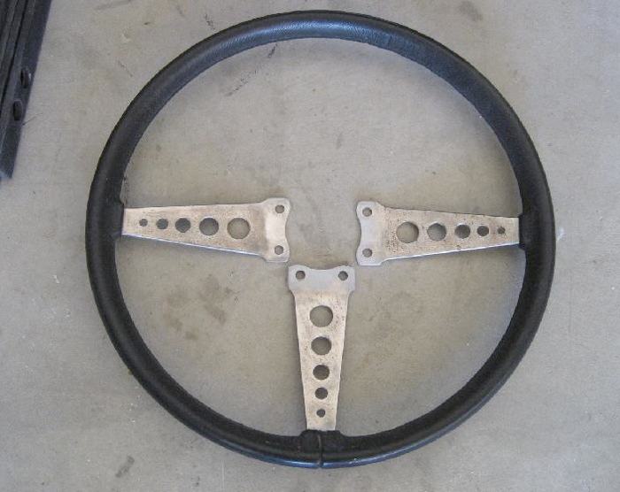
Figure 1: Stock 72 wheel with foam intact
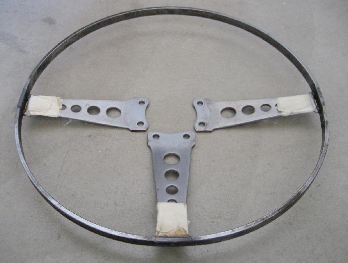
Figure 2: Wheel with foam removed
Design
The size of the wheel was the first thing to consider. Since I was using a stock frame and didn't want to fabricate a new outer rim, I was looking at a finished outer diameter in the 15 to 15-1/2 inch range. I have no problem fitting my legs under the stock wheel so there was no need to change. Also, recall that one of my goals is to retain a reasonable stock appearance. The thickness of the rim was the next consideration. I found the stock foam was a bit too thin for my taste, so after trying out different sizes I selected a thickness of 1 inch. I had some garden hose of precisely that size and that's how I determined it was a comfortable thickness without being too thick like some modern wheels. The stock foam was about 7/8 thick, so the slight increase is likely to go unnoticed by even the most discerning eyes in the MG crowd. The final rim thickness is actually 1 inch wide and 1-1/8 inches deep. I found that the slightly ovoid shape was more comfortable. I noted the ovoid design was also utilized on my current daily driver, a Porsche 997S Cabriolet with a Makassar wood wheel. (I'll resist venting about the $1700 USD that tasty little option required; let me quickly conclude the matter by saying that the Germans are not shy about asking for baskets of money for their very fine cars!)
Anyone who has thought about making a wood wheel has likely determined there are two schools of design: 1) a bent wood rim and 2) a segmented wood rim. I do not have a steamer so the bent wood design was not gaining any traction with me. Also, the bent wood design will limit your choices for wood as certain species bend satisfactorily while others will cause you great pain in your efforts. I have seen numerous examples of segmented wheels and I think they look just fine, and I also knew that I could fabricate such a wheel without having to make or buy any additional tools. So, without any further internal debate or outlay of cash, the segmented wheel design was my choice.
Next, how many segments would I use? Once again, my laziness and frugality helped me to decide. I drew up a few example layouts using four, six, or eight segments. After some review of each design I chose the six segment layout since to my sensibility it was the best use of material, it didn't have too many joints, and it meant that I could have reasonably straight grain in each segment. Perhaps I should also mention that I had some scrap pine stock to use for a prototype and the width of the material also meant that six segments was the most logical choice.
Following are two pages of rough design work when I was figuring out how to proceed. The first shows layout for a six segment or four segment wheel. The second shows the cross section including major diameters and the associated calculations. Figure 3 shows the layout for a four or six segment design. Figure 4 shows some measurements and calculations as well as the design of the cross section.
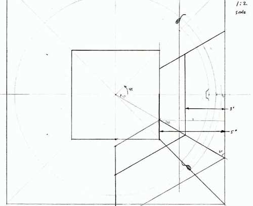
Figure 3: Layout options using four or six segments
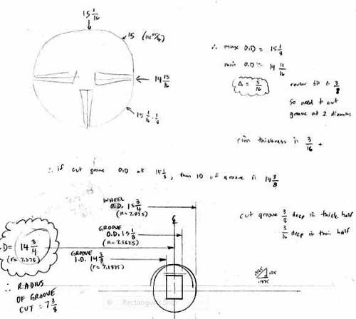
Figure 4: Cross section and relevant diameters
Prototype
Anyone who has watched Norm on the television show New Yankee Workshop will know the phrase: "Before we use any power tools, let's take a moment to talk about shop safety. Be sure to read, understand, and follow all the safety rules that come with your power tools. Knowing how to use your power tools properly will greatly reduce the risk of personal injury. And remember this: there is no more important safety rule than to wear these — safety glasses."
With the basic design established, I was ready to test the legitimacy of the design by making a prototype from scrap wood before buying any quality lumber. I had some suitable scrap pine that was 3-1/2 inches wide and just under 5/8 thick. Using some basic geometry I determined that I was going to have to cut the board into trapezoid shapes with a 30 degree angle (remember six segments means each wedge is 60 degrees of the 360 circle). The long side of the trapezoid was to be 9-1/4 inches. This allowed a little scrap to be cut-off on the outer diameter.
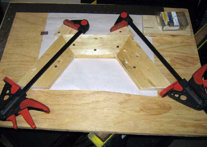
Figure 5: Prototype glue-up of three segments
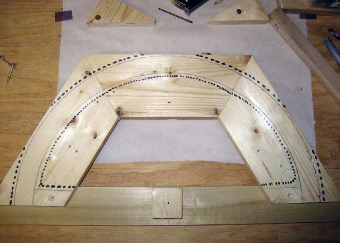
Figure 6: Prototype layout and center bar attached
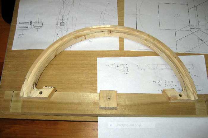
Figure 7: Prototype with groove, OD, and ID machined

Figure 8: Prototype with round-over complete on rim
I was too lazy to make a complete wheel for the prototype, so I made only a partial wheel. The design called for me to fabricate the wheel in two halves (think about the two halves of a bagel after you slice it). For my prototype, I made half of one of the halves.
I glued up the three segments in a homemade jig. I used Gorilla Glue since it is very strong, totally water proof, and is stainable should there be any glue visible in the joints. Gorilla Glue
is a particular brand of glue sold in North America; it's urethane type glue that is suitable for bonding different materials to one another: wood, metal, stone, etc.
During the test phase, I also determined what cuts I would be making with the router. There are three basic cuts: 1) the groove in which the outer steel rim will be glued, 2) the outer diameter (OD), and 3) the inner diameter (ID). Once the inner and outer diameters are complete, the router is also used to round-over the edges thus completing the circular cross section of the wheel. The following four pictures show the glue-up of the three segment test piece (Figure 5); layout of the diameters and rough cut areas (Figure 6); the test piece with machined groove, ID, and OD (Figure 7); and finally the test piece after round-over of the edges (Figure 8).


your help, perhaps one day will come and be ready for Spring! Thanks for your detailed and
documented explanation of hoe to get 'er done!
you.
Now to find a steering wheel on Ebay for the progect.
Any project need a plan and a starting point. Reading this article is a great start.
Can you tell me what you did to the metal? It looks so shiny and pretty.. I am trying to restore mine (I have that same one with the foam) I just removed the surface rust, but the metal looks like stained. Any help is appreciated!
morris minor wheel....
morris minor wheel....
project instructions but with a different steering is it possible to
cut and weld peices so that it becomes a quick release because the
steering i have has round edges and the midle (center part)is for stock
cars... need your help thanks
similar, but based on the original sprung/dished profile Minor steering
with a thinner rim. Though this would entail some unique difficulties of
its'own I think. One day. Great article.
me money!
Thank you!
process, use of a prototype, making the few tools you had work, and
general description of how and why you did what you did. Finished
product looks outstanding.
Want to leave a comment or ask the owner a question?
Sign in or register a new account — it's free